 2026-06-22
 A drive shaft — also written as driveshaft or propeller shaft — is the mechanical component responsible for transmitting rotational torque from the transmission or transfer case to the differential or wheel hub. In a rear-wheel-drive vehicle, a single long propeller shaft spans the distance between the gearbox output and the rear axle. In front-wheel-drive and all-wheel-drive vehicles, shorter half-shafts connect the differential to each driven wheel through constant velocity (CV) joints that accommodate steering angles and suspension travel.
The loads a drive shaft must endure are substantial. At highway speeds, a driveshaft in a performance vehicle may rotate at 3,000–6,000 RPM while simultaneously transmitting hundreds of Newton-meters of torque. Any imbalance in the shaft at those speeds introduces vibration that is felt throughout the vehicle, accelerates bearing wear, and in extreme cases can cause the shaft to resonate destructively. This is why drive shaft manufacturing is not a process where approximate tolerances are acceptable — dimensional accuracy, material consistency, and rotational balance must all meet tight specifications.
Beyond passenger vehicles, driveshafts are critical components in trucks, agricultural equipment, marine vessels, industrial machinery, and aerospace systems. Each application imposes its own demands on the manufacturing process, which is why understanding the full production chain — from raw material to finished, inspected component — matters both for manufacturers and for engineers specifying driveshafts in new designs.
The choice of raw material is one of the most consequential decisions in driveshaft production. It determines the shaft's strength, weight, fatigue life, machinability, and cost. The three dominant material families used in modern drive shaft manufacturing are alloy steel, aluminum alloy, and carbon fiber composite.
Medium-carbon alloy steels — most commonly grades such as SAE 1040, 1045, 4130, and 4340 — remain the most widely used driveshaft material across automotive, commercial vehicle, and industrial applications. These steels offer an excellent combination of tensile strength (typically 600–1,000 MPa in the normalized condition, rising to 900–1,400 MPa after heat treatment), toughness, and machinability. SAE 4340, a nickel-chromium-molybdenum steel, is the preferred grade for high-performance and heavy-duty driveshafts where maximum fatigue strength is required. Its deep hardenability allows through-hardening of larger cross-sections, ensuring consistent properties from surface to core.
Aluminum driveshafts — typically made from 6061-T6 or 7075-T6 alloy — offer a significant weight reduction compared to steel, typically 40–50% lighter for an equivalent shaft diameter. This weight reduction lowers the rotational inertia of the drivetrain, improving throttle response and fuel efficiency. Aluminum driveshafts are increasingly used in performance cars, sports trucks, and racing applications. However, aluminum has lower stiffness than steel (elastic modulus of approximately 70 GPa versus 200 GPa for steel), which means an aluminum shaft must have a larger tube diameter to achieve the same torsional rigidity — a design trade-off that must be factored into packaging decisions.
Carbon fiber reinforced polymer (CFRP) driveshafts represent the premium end of the material spectrum. A carbon fiber propshaft can be 60–70% lighter than its steel equivalent while offering higher specific stiffness — allowing it to operate at higher critical speeds without entering resonance. This is particularly valuable for long one-piece driveshafts in trucks and rear-wheel-drive cars, where a steel shaft's critical speed would require splitting the shaft into two pieces with a center support bearing, adding complexity and weight. CFRP driveshafts are used in production vehicles such as the BMW M3/M4, Corvette C8, and various heavy-duty pickup trucks. The manufacturing process for CFRP shafts — filament winding or prepreg layup around a mandrel — is fundamentally different from metal shaft production and requires specialized facilities.
Steel and aluminum driveshaft production follows a well-established sequence of operations. While the specific parameters vary by application and manufacturer, the core process steps are consistent across the industry.
Most automotive driveshafts start as seamless steel or aluminum tube, since a hollow cross-section provides superior torsional stiffness per unit weight compared to a solid bar. Seamless tube is produced by rotary piercing (the Mannesmann process) or extrusion, which ensures there are no longitudinal weld seams that could be a fatigue initiation site under cyclic torsional loading. The incoming tube is inspected for dimensional conformance — outer diameter, wall thickness, ovality, and straightness — before being cut to length. For solid stub shafts and yoke preforms, round bar stock is used instead, often sourced as hot-rolled bars that will subsequently be forged.
The end components of a driveshaft — the yokes that connect to universal joints, the flanges that bolt to the differential, and the stub shafts that interface with CV joints — are almost universally produced by hot forging rather than machining from solid bar. Hot forging at temperatures of 1,100–1,250°C for steel aligns the grain flow of the metal with the shape of the component, dramatically improving fatigue strength compared to a machined part where grain flow is interrupted. Forging dies are precision-machined to produce near-net-shape forgings that minimize subsequent machining stock. After forging, the parts are trimmed to remove flash (the thin fin of excess material squeezed out between die halves) and shot blasted to remove scale.
Both the tube sections and the forged end components require precision CNC machining to achieve final dimensional tolerances. Tube ends are turned and bored to accept the end yokes, and splined sections — which allow axial sliding between the transmission output and the driveshaft during suspension movement — are cut using broaching, hobbing, or CNC milling. Spline tolerances are critical: the fit between the driveshaft spline and the mating component must be tight enough to prevent backlash and noise, yet allow smooth axial sliding. Typical spline tolerances for automotive driveshafts are in the range of IT6–IT7 per ISO 286, with pitch errors below 10–15 microns.
Joining the machined tube to the forged end yokes is one of the most critical operations in driveshaft fabrication. The two dominant joining methods are friction welding and MIG/TIG welding. Friction welding (inertia or continuous-drive) produces exceptionally high-quality joints with narrow heat-affected zones, no porosity, and consistent strength equal to or exceeding the parent material — making it the preferred method for high-volume automotive production. In friction welding, the tube and yoke are pressed together while one rotates at high speed; frictional heat plasticizes the interface, and the rotation is stopped while forge pressure is applied, consolidating the joint in under two seconds. MIG welding is used for lower-volume or larger-diameter driveshafts where friction welding tooling cannot be justified economically.
Most alloy steel driveshafts and their end components undergo heat treatment to achieve the required mechanical properties. The standard sequence for a high-strength driveshaft is quench-and-temper: the part is austenitized at 820–870°C, oil or water quenched to form a martensitic microstructure, and then tempered at 400–650°C to relieve quench stresses and achieve the target hardness-toughness balance. For splined sections and journal surfaces that must resist wear, induction hardening is applied selectively — a high-frequency induction coil rapidly heats the surface layer to above the austenitizing temperature, followed by immediate quenching, creating a hard surface (typically 58–62 HRC) over a tough core. This dual-property condition — hard wear surface over a tough core — is ideal for splines that must resist both fretting wear and impact loading.
Heat treatment introduces distortion in most steel components, and driveshafts are no exception. A shaft that is even slightly bowed will vibrate at high RPM. After heat treatment, every driveshaft is checked for runout on a straightening press equipped with dial indicators or laser sensors. Shafts exceeding the runout specification — typically less than 0.3–0.5 mm total indicator reading (TIR) over the full length for automotive applications — are straightened using a hydraulic press, applying localized bending force at the high point until the shaft falls within tolerance. This step requires skilled operators or automated vision-guided presses that can identify the location and magnitude of the bend and apply the correct corrective force.
Dynamic balancing is arguably the single most important quality step in drive shaft manufacturing for NVH (noise, vibration, and harshness) performance. An unbalanced driveshaft generates centrifugal forces at twice per revolution that grow with the square of rotational speed — what feels like a negligible imbalance at 500 RPM becomes a violent vibration at 4,000 RPM. Every driveshaft is balanced on a dynamic balancing machine that spins the shaft at a defined speed, measures the magnitude and angular position of the imbalance in two correction planes, and then either adds balance weights (clips welded or mechanically attached to the tube) or removes material by drilling or grinding until the residual imbalance falls within the permissible limit. For passenger car driveshafts, the balance specification is typically below 5–15 g·cm per plane; for high-performance or heavy-duty applications, this may be tightened to 2–5 g·cm or less.
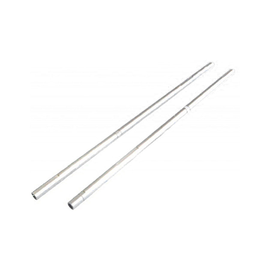
Precision driveshaft production is governed by a set of dimensional and functional tolerances that ensure each shaft performs correctly in service. The table below summarizes the key parameters and their typical tolerance ranges for automotive passenger vehicle driveshafts:
| Parameter | Typical Tolerance / Specification | Why It Matters |
| Overall length | ±0.5 mm | Ensures correct engagement depth in splined joints |
| Tube OD runout (TIR) | ≤ 0.3–0.5 mm over full length | Limits vibration at operating speed |
| Yoke phase angle alignment | ±0.5° to ±1.0° | Prevents 2nd-order vibration from U-joint angularity |
| Spline pitch error | ≤ 10–15 µm | Controls backlash and load distribution |
| Surface hardness (induction zone) | 58–62 HRC | Provides wear resistance on journals and splines |
| Residual imbalance (per plane) | ≤ 5–15 g·cm | Minimizes centrifugal forces at speed |
| Weld tensile strength | ≥ parent material strength | Ensures joint is not the fatigue weak point |
| Surface finish (journal areas) | Ra 0.8–1.6 µm | Reduces fretting and seal wear |
At the industry level, driveshaft manufacturers supplying OEM automotive customers operate under IATF 16949 (the automotive quality management system standard), and their products must comply with design validation requirements such as torsional fatigue testing to a defined life target — typically several hundred thousand cycles at the maximum design torque. Non-destructive testing methods including magnetic particle inspection (MPI) for steel parts and dye penetrant inspection (DPI) for aluminum are used to screen for surface cracks before components enter service.
A driveshaft does not transmit torque through a perfectly straight path — it must accommodate angles between the driving and driven components caused by suspension movement, steering deflection, and powertrain mounting tolerances. This angular accommodation is handled by joints at the ends of the shaft, and the type of joint significantly influences both the manufacturing process and the shaft's performance characteristics.
The cross-and-bearing universal joint is the traditional solution for propeller shafts in rear-wheel-drive and four-wheel-drive vehicles. A U-joint transmits torque at an angle by means of a cross-shaped trunnion rotating inside four needle-bearing cups. While simple and robust, a single U-joint operating at an angle produces a velocity fluctuation — the output shaft speed is not constant but varies sinusoidally twice per revolution, with the amplitude of the variation increasing with joint angle. In a two-joint driveshaft, this velocity fluctuation is cancelled by arranging the two joints in phase (yokes in the same plane), which is why yoke phase angle is a critical manufacturing parameter. U-joint manufacturing involves precision grinding of the trunnion journals to achieve roundness within 2–3 µm and surface finish below Ra 0.4 µm, as these surfaces run on needle bearings under high contact stress.
CV joints — used universally in front-wheel-drive half-shafts and increasingly in all-wheel-drive systems — transmit torque at an angle without velocity fluctuation. The most common types are the Rzeppa ball joint (outer end) and the tripod joint (inner, plunging end). CV joint manufacturing is highly precise: the ball tracks in a Rzeppa joint must be ground to profile tolerances below 10 µm, and the cage windows must be held to tight positional tolerances so that the six balls are always maintained in the bisecting plane between the input and output members. CV joints are typically manufactured as separate assemblies — with inner race, cage, balls, and outer race each produced on dedicated production lines — and then assembled, packed with grease, and fitted with a protective rubber boot before being pressed onto the driveshaft tube.
A driveshaft operates in a harsh underbody environment — exposed to road salt, water, mud, and stone impacts — and must maintain its structural integrity and surface condition over a vehicle's full service life. Corrosion protection is therefore an integral part of the manufacturing process, not an afterthought.
Understanding what separates original equipment manufacturer (OEM) driveshaft production from the aftermarket replacement market is important for anyone specifying or purchasing driveshafts for repair or performance applications.
| Factor | OEM Manufacturing | Aftermarket Manufacturing |
| Material certification | Fully traceable to heat lot | Varies widely by supplier |
| Balance specification | Per OEM drawing (typically ≤10 g·cm) | Often looser (≤25–50 g·cm) |
| Joint quality | OEM-grade CV or U-joint assemblies | Ranges from OEM-equivalent to economy grade |
| Yoke phase angle | Controlled to ±0.5° | Sometimes not controlled |
| Fatigue validation | Full rig and vehicle testing | Rarely performed |
| Boot material | High-temp TPE or EPDM | Sometimes standard rubber |
| Price point | Higher (dealer/OEM pricing) | Lower to mid-range |
For standard replacement on a daily-driver vehicle, a reputable aftermarket driveshaft from a supplier that follows ISO or IATF quality standards and uses proper dynamic balancing is typically entirely adequate. For high-performance, towing, or off-road applications where torque loads exceed the original design envelope, OEM-equivalent or purpose-built performance driveshafts with upgraded material and tighter balance specifications are the correct choice.
Even with rigorous process controls, defects can occur in driveshaft manufacturing. Knowing what the common failure modes are — and how manufacturers screen for them — is valuable both for quality engineers and for end users trying to evaluate a shaft's condition.
Drive shaft manufacturing is evolving in response to electrification, lightweighting demands, and advances in automation and materials science. Several trends are already influencing how driveshafts are designed and produced.
Electric vehicle powertrains are changing driveshaft requirements in meaningful ways. Unlike internal combustion engine vehicles where driveshaft torque builds gradually as engine RPM rises, electric motors deliver maximum torque instantaneously from zero speed. This means EV driveshafts and CV joints are subjected to far more severe torque shock loading than their ICE equivalents, driving changes in material selection (higher-strength steels and larger-diameter CV joint ball sets) and joint design (wider ball tracks and larger cage windows to distribute load).
Lightweighting pressure from fuel economy and EV range targets is accelerating adoption of aluminum and carbon fiber driveshafts in segments that previously used only steel. Automated filament winding lines for CFRP shafts are becoming more productive and cost-effective, and several Tier 1 suppliers are now offering CFRP propshafts at price points competitive with multi-piece steel shaft assemblies when the center bearing and support bracket are eliminated.
Digital manufacturing and inline process control are being integrated into driveshaft production lines. Vision systems check weld geometry and surface condition automatically, laser measurement systems verify tube runout and length at production speed without operator measurement, and statistical process control (SPC) software monitors key parameters in real time to identify process drift before out-of-tolerance parts are produced. These Industry 4.0 tools are raising the quality floor across the driveshaft supply base while reducing inspection labor costs — a combination that benefits both manufacturers and the end customers who depend on their vehicles to perform reliably.
 CategorieBeveel post aan

Fenglan wel Fabrikant van elektrische precisieonderdelen in China, Fabrikanten van precisie-onderdelen voor de auto-industrie en Leveranciers van industriële precisieonderdelen. Uw betrouwbare partner in de productie van onderdelen en componenten sinds 2010
 Tel: +86-13861233850
  E-mail: [email protected]
  Add: No.60, East Zhuanghe Road, Chunjiang Town, Wei Village, Xinbei District, Changzhou City, China
  Privacy


 +86-13861233850
 17-09-2025